Anemometry Technology to Measure the Wind in Front of the Rotor
The ROMO Wind iSpin system uses proven ultrasonic technology to measure wind where it first hits the turbine – directly at the spinner. In this way, it is able to measure parameters at the nacelle which until now have been difficult or impossible to measure accurately. Operators gather exact information on the wind conditions in front of the rotor including wind speed, yaw alignment, flow inclination, turbulence, rotor position and temperature. This enables them to check whether their turbines are aligned for the best possible yield. At the same time, the data allows for optimised wind farm management and load reduction, which prolongs the total life of the turbines.
By Harald Hohlen, ROMO Wind Deutschland GmbH, Germany
Unfortunately, most wind turbine measurement equipment in use today is unable to properly measure the wind hitting the turbine. This industry-wide, fundamental wind measurement problem is caused by the fact that the wind turbine’s own wind measurement equipment when located on the nacelle behind the rotor is heavily affected by rotor turbulence and other unpredictable wind conditions. The problem results in inaccurate and imprecise wind speed and wind direction measurements on the wind turbine and, as a consequence, in reduced yaw alignment capabilities. ROMO Wind’s spinner anemometry technology iSpin, which was developed at DTU and improved by ROMO Wind using actual field experience, measures wind quantities like wind speed, yaw misalignment and flow inclination at the spinner in front of the wind turbine rotor, where the wind conditions are more predictable. As a result, iSpin is an ideal tool to measure yaw misalignment and further wind quantities relevant for wind turbine performance measurements.
Yaw Misalignment at Wind Turbines
Yaw misalignment has recently become the subject of operators’ and manufacturers’ attention and it is now known to have been an underestimated topic for a long time. Since 2011 ROMO Wind has been offering services to detect yaw misalignment using the spinner anemometry technology iSpin. An overview of the results based on more than 250 turbine measurements of dynamic yaw misalignment, static yaw misalignment and correction potential are given below.
Reasons for Yaw Misalignment
Yaw misalignment is described as the deviation between the wind direction affecting the turbine and the actual nacelle direction. There are several reasons for yaw misalignment, which can be divided into sensor driven, site driven, control driven and caused by human mistake. Whereas human mistakes or sensor-related issues can be improved by more elaborated installation, commissioning and check procedures, site-dependent reasons are especially difficult to isolate and to take into account using conventional nacelle anemometry. The main reason for this is the nacelle transfer function for the wind direction (NTFWD). This function is normally identified for a specific turbine type during prototype measurement by finding the correlation between met mast wind direction and nacelle direction in free-flow conditions. But the relationship between the wind speed NTF and the NTFWD is unlikely to be valid under certain site-specific conditions (e.g. complex terrain or in wind parks with many turbines) because of the changed flow conditions reaching the conventional nacelle anemometry.
![]() |
![]() |
![]() |
Types of Yaw Misalignment
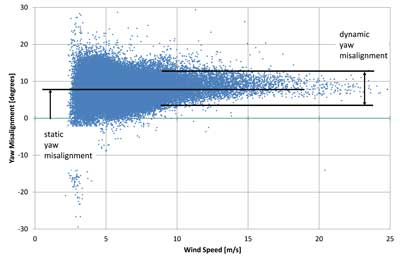
Because the wind direction is constantly changing, a turbine cannot always point correctly into the wind. However, on average the yaw misalignment should always be close to zero degrees to fully extract the wind energy as well as subjecting the machine to minimal loads. As shown in Figure 1, a difference can be distinguished between static yaw misalignment and dynamic yaw misalignment. Static yaw misalignment describes the general deviation between wind and nacelle direction considering binned data from 10-minute intervals. Dynamic yaw misalignment describes the variation around the static yaw misalignment. Static yaw misalignment can be corrected either mechanically or, preferably, by introducing an offset to the wind direction parameter in the turbine’s programmable logic controller. Dynamic yaw misalignment is a result of the control system attempting to align the turbine in accordance with the inaccurate and highly unstable wind direction information from the conventional turbine wind direction sensor on top of the nacelle.
Different Yaw Control Strategies
Turbine manufacturers have different yaw control algorithms following different yaw strategies. The main goal of the yaw control algorithms should be to provide an optimal balance between energy capture and keeping the fatigue load level of turbine components within their design limits. The spread of the data scatter normally indicates the quality of the wind direction sensor information and the yaw algorithm of the turbine control system. As shown in Figure 2, the dynamic yaw misalignment can vary significantly from turbine to turbine type. Best in class turbines monitored by iSpin show a standard deviation of 2–3 degrees. At the bottom of the class iSpin reveals deviations closer to 9 degrees.
Figure 3 shows the dynamic yaw misalignment in relation to the turbine size. The average dynamic yaw misalignment of the evaluated turbines is 3.65 degrees. With the exception of two turbine types, all investigated turbines show average or good yaw control.
Yaw Misalignment is a Common Problem
Yaw misalignment is not a problem confined to old turbines or just certain turbine manufacturers. Figures 4 and 5 show the level and occurrence of the static yaw misalignment in relation to the turbine size with respect to different turbine manufacturers. Although the statistical basis for some of the results is small, it can be seen that almost every turbine manufacturer has at least one turbine type suffering from yaw misalignments greater than 4 degrees. Interestingly, more than 52% of the investigated turbines do show values above 4 degrees and, furthermore, 24% of all investigated turbines have static yaw misalignment values which exceed 8 degrees. These very high values can be seen in turbines ranging from 1.5 to 3.6MW and also within the portfolio of different turbine manufacturers.
Effect on Power and Energy Production
![]() |
![]() |
![]() |
Yaw misalignment reduces the swept area which is driving the wind turbine power production. Figure 6 shows measurement results based on iSpin and SCADA data derived from a turbine which was operated with three different static yaw misalignment angles (30, 9 and 0 degrees). Here each dot represents binned power values normalised to power for 0-degree yaw misalignment. ROMO Wind found that the reduced power can be conservatively approximated by a cosine-squared (cos2) relationship, and this was confirmed as a valid approach by GL-GH and others,
Annual energy production (AEP) is based on the power curve and the wind distribution. The assumption that AEP losses follow cos² of yaw misalignment is also a very good approximation here (see Figure 7). Based on this approach the yaw misalignments of Figure 4 have been transferred to AEP losses (see Figure 8). Translating this into optimisation potential means approximately 1.7% more AEP could be achieved by having the static yaw misalignments corrected.
Effect on Loads
Turbine design according to IEC or GL guidelines demands calculation of fatigue loads mainly based on normal operation load cases in the operational wind speed range. Within these calculations static yaw misalignment values of up to ±8 have to be considered. Figure 4 shows the overview of yaw misalignment distinguished by the degree of the deviation. Although many turbines show an average misalignment value between 4 and 6 degrees, about a quarter of all turbine types were found to operate with misalignments exceeding 8 degrees. Comparing this result to the requirements given by the design guidelines, this would mean that those turbines are running outside their operational limits and most probably outside their design limits.
Turn your Turbine into a Virtual Met Mast
Although the spinner anemometry was first installed to identify yaw misalignment, more and more customers now understand the extra value this measurement system can offer them. By enhancing iSpin with additional relevant sensors such as wind speed, turbulence intensity, wind direction, flow inclination, temperature and air pressure these can be measured independently from the turbine control and SCADA system. Consequently the demand to use iSpin for on-site evaluations, as well as for relative power curve measurements, is growing continuously. As spinner anemometry technology is included in IEC61400-12-2 for absolute power curve measurements using nacelle anemometry, several extensive field studies are currently being carried out. First results show that the category A uncertainty (i.e. the variation in the power curve scatter) of iSpin is approximately 30% less than that of most met masts or lidars. In addition, the iSpin NTF shows a much more robust behaviour when it comes to wake effects. This results in much lower scatter visible in power curves in all wind directions.
About iSpin The ideal rotor plane orientation for optimal energy capture is perpendicular to the wind direction. In this orientation, the wind flows evenly over the symmetrical spinner, and the iSpin sensors during their rotation therefore detect the same wind speed at any point of the spinner’s rotational path. However, if the wind is hitting the rotor from an angle different from perpendicular relative to the rotor plane the wind will accelerate differently on the two sides of the spinner. This means that each iSpin sensor measures a cyclically varying wind speed as the spinner rotates. The amplitude of the cyclical wind speed variation is proportional to the yaw misalignment angle. |
Biography of the Author
After his PhD at the Technical University Berlin, Harald Hohlen started his career with the turbine manufacturer DeWind as a technical specialist with a particular focus on measurements and loads. With his expertise in condition monitoring, loads and simulation of wind turbines he became Head of Development in the Measurement, Simulation & Control group of DeWind. In July 2015 Harald started to work with ROMO Wind as a Senior Wind Measurement Specialist, supervising all the scientific research and development projects. During his career Harald has written several papers on wind turbine load conditions and measurements in wind turbines.